Graphs and Procedural Generation: The Essential Foundations for Creating Worlds
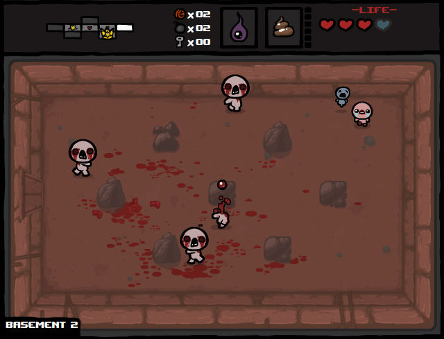
The initial problem is simple: pure randomness produces noise, not design. Take the example of The Binding of Isaac, an action/adventure game released in 2011.
In this game, you move from room to room. While the rooms themselves are pre-built, their sequence is procedurally generated. Now imagine if the decision to have a second room after the first was purely random: you could end up stuck in the first room because there’s no exit. Taken to the extreme, randomness without design leads to rooms with no purpose, incoherent quests, or nonsensical dialogue. On the other hand, a game with strict design and rules will offer a very linear experience to the player.
The goal in a video game using procedural generation is to avoid pure randomness and take control over it, while still adding a layer of noise to ensure the player never has the same experience twice. To achieve this, you need an approach that allows a team to collaboratively design the set of algorithms. One effective solution is to use graphs.
In this article series, we’ll break down how graphs can help structure procedural generation algorithms, for example to:
- Shape 2D or 3D worlds.
- Build dynamic mission and quest systems.
- Create branching dialogues that react to the game state.
The aim of this first article is to lay out the mathematical foundations for understanding graphs. In the next articles, we’ll focus on how to translate these concepts into game design decisions, look at graph-based procedural generation algorithms, and see how to implement them in a game engine. In our case, we’ll use Unity.
Why Graphs Are Everywhere in PCG (Procedural Content Generation)
A graph is a way to represent relationships between elements:
- A node represents a discrete element (a room, an objective, a line of dialogue, etc.). It’s also called a vertex or simply a point.
- An edge represents a logical connection between two nodes (a door between rooms, a condition for completing an objective, a transition between dialogue lines, etc.).
In procedural generation, this lets you separate:
- The logical structure. This is the description of what’s possible.
- The rendering. This is what the player actually experiences visually, audibly, or through gameplay.
At Old Skull Games, for example, we adopted this approach to create procedural levels in SpongeBob: Patty Pursuit. We first defined the logical structure of the level as a graph, then used that graph to generate the level’s visual layout.
- Design: Designers, level artists, and programmers aligned on the intended experience.
- Prototyping: We sketched a graph on paper showing the sequence of sections/rooms.
- Implementation: A small team of three people built the validated prototype.
Minimal Math Recap
Good news: we’ve already seen the two most important concepts : nodes and edges.
Cycle
Let’s start with the idea of a cycle. A cycle is a loop in a graph, meaning a sequence of edges that starts and ends at the same node. For example, in a dungeon, a cycle might represent a path that lets the player backtrack.
Tree
If a graph contains no cycles, it’s called a tree. For example, a branching story might lock certain branches and gradually force the player toward an ending. This structure also lets you organize nodes in a hierarchy, with a root node (e.g., the story’s beginning) and leaf nodes (the possible endings).
Graph Orientation
In the previous example, I drew arrows instead of plain lines to indicate edge direction. This is called a directed graph. In a directed graph, edges have a direction, meaning the relationship they represent isn’t symmetric (A can lead to B, but B doesn’t necessarily lead to A). For example, in a quest, you might want certain steps to be one-way (once the player saves the princess, they can’t go back and let her be captured again).
Step 1/4 - Point de départ
Conversely, there are undirected graphs, where edges have no direction. In this case, the relationship is symmetric (if A is connected to B, then B is also connected to A). For example, in a dungeon, you might want some routes to be bidirectional (a door that can be opened from either side).
Step 1/5 - The player start in Room A
Of course, you can mix both types of edges. In a level with doors and keys, some routes are bidirectional, others strictly one-way. Technically, even if a graph contains both directed and undirected edges, you can treat it as a directed graph, since undirected edges can be represented as two directed edges in opposite directions.
Step 1/3 - Free navigation of the dungeon
Weights
While not always necessary, you can add weights to edges. For example, in a dungeon, you might want some routes to be longer than others, or some objectives to be harder to reach.
Step 1/1 - In this example, the shortest path from the entry to the boss room is through room 2, even if it's not the most direct path when starting from the entry.
Level Design and Graphs
Okay, we’ve covered the math basics, but how does this translate to level design? The exact way you represent a level as a graph depends on the game type and your team’s workflow. The most common use I see is:
- Nodes represent rooms or sections of the level.
- Edges represent the connections between those rooms (doors, corridors, etc.).
Now you need to think about your level’s structure: Are the rooms organized linearly, or are there branches? Can the player backtrack? Are some routes harder than others? By answering these questions, you can choose the graph structure that best fits your vision. To do this, we’ll create a graph where each node is named for its function. This is often called a Level Graph.
For example, if you want a linear level, you can use a directed acyclic graph, where each room leads to the next.
This same structure can represent a linear story, where each step leads to the next.
You might also want a more open level, with branches and alternate routes. In this case, you can use a directed graph with cycles, letting the player backtrack or choose different paths.
This example highlights a key element of procedural generation: if you create exploration in your level, you need to ensure several things:
- The player can backtrack and not get stuck. The easier it is to backtrack, the more motivated the player will be to explore.
- Dead ends should reward exploration, for example by offering treasures or secrets. This encourages players to take risks and discover new things.
Dead Cells is an excellent example of these design rules applied to procedural generation. In the last part of this article, we’ll analyze how graphs are used in this game to create interesting and varied levels.
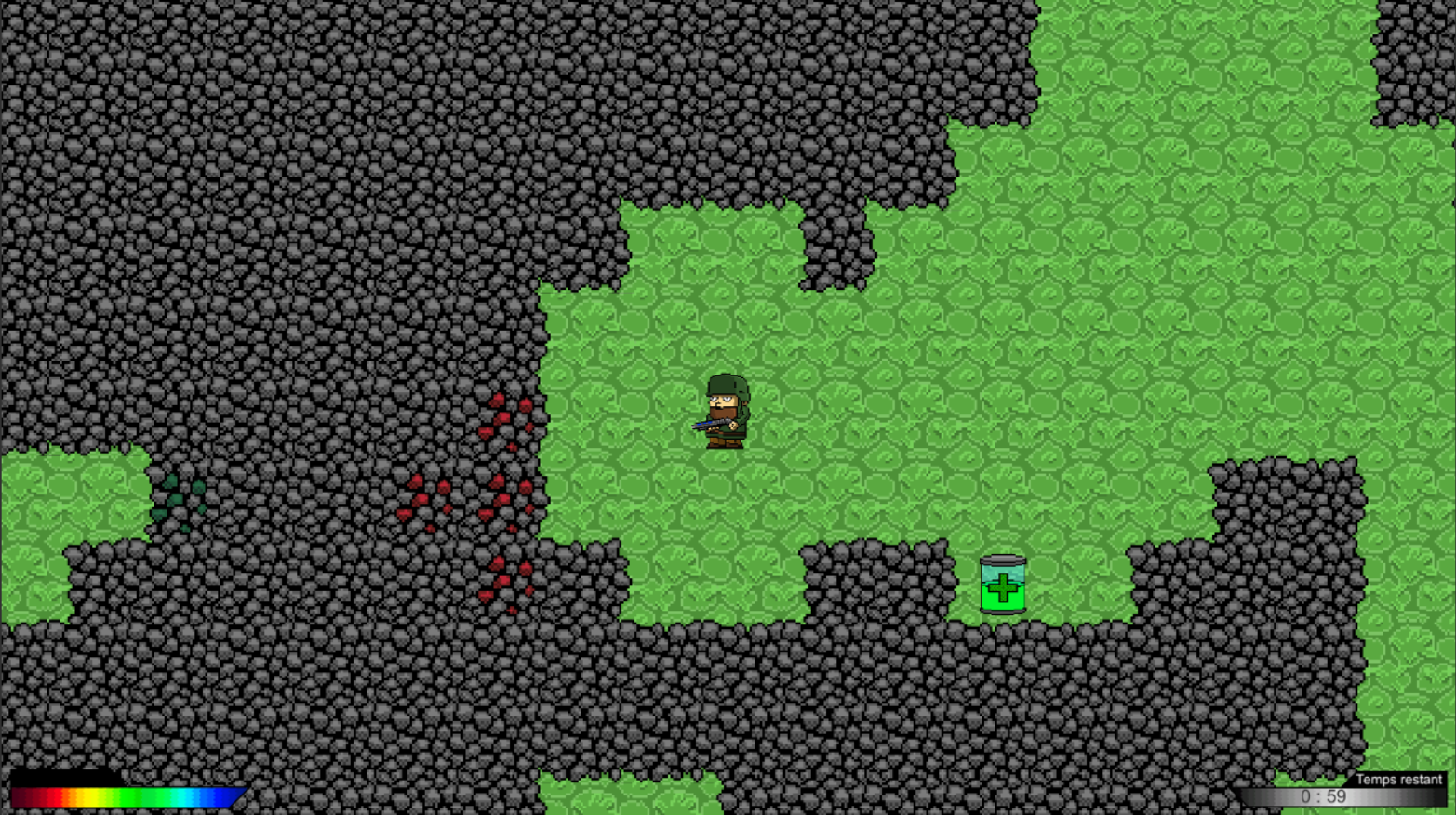
Study Case: Applying Graphs to Procedural Generation in Dead Cells
If you don’t know the game, it’s a roguelike with Metroidvania ambitions, where you explore a world with zones that unlock progressively. Each run feels unique thanks to procedural generation, but the levels are designed to ensure a coherent and engaging experience. Check it out on Steam if you haven’t already.

First, I want to point out that I don’t know the exact details of Dead Cells’ procedural generation algorithms, my goal here is to reverse-engineer how graphs might be used to structure procedural level generation in a game like Dead Cells. If you’re interested in a deeper analysis, check out these resources:
- This article by Sebastien Benard, Lead Designer of Dead Cells, which explains the inspiration behind Dead Cells’ level design and how the team tackled the challenge of creating procedurally generated levels that still feel handcrafted.
- This video, which attempts to reproduce the process, goes into more detail about the algorithms and includes an attempt to recreate the room generation process.
Now, let’s put ourselves in the shoes of Motion Twin, the studio behind Dead Cells. We want to create a roguelike with Metroidvania ambitions. We want players to explore a world with zones that unlock progressively, but also want each run to feel unique thanks to procedural generation. To do this, let’s list the types of rooms in the game (not exhaustive, just for illustration):
- Combat
- Corridor
- Entry
- Exit
- FlaskRoom
- Teleporter
- Treasure
- Shop
- Crossing
- etc.
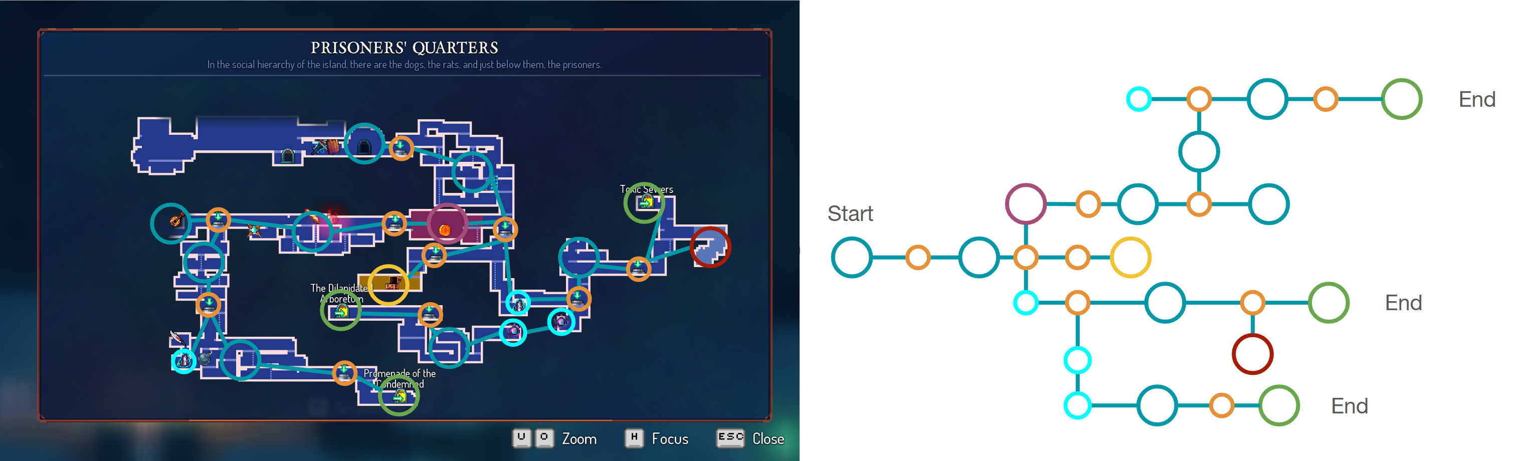
Now let’s break down the structure of a Dead Cells level and create a Level Graph using the room types above.
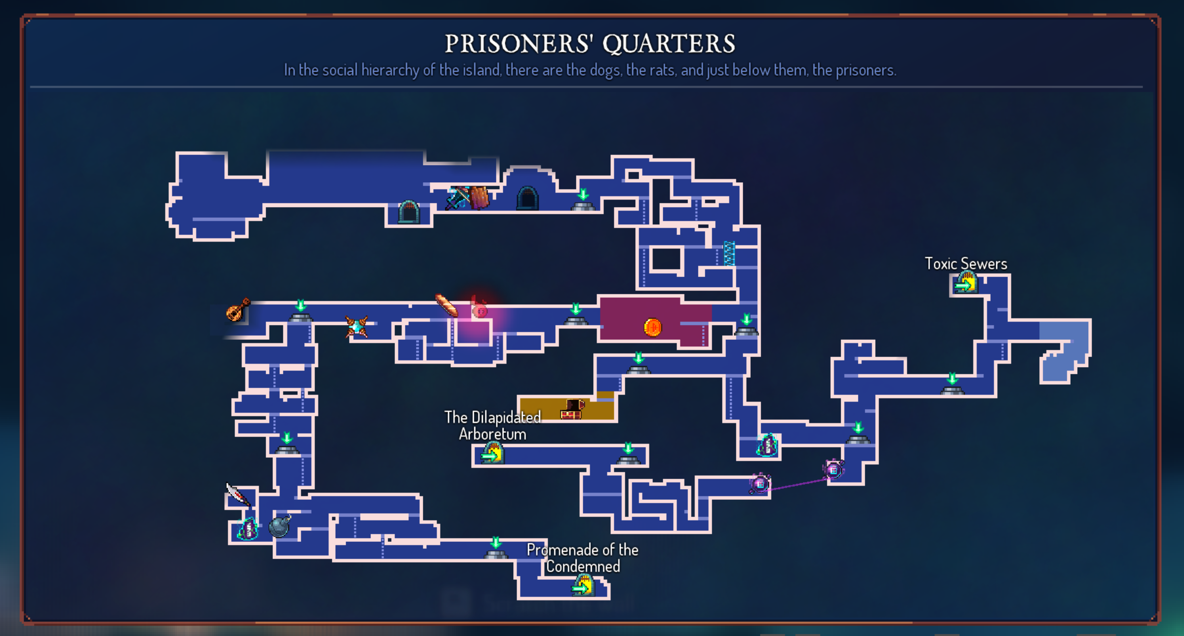
Here’s that same level transformed into a Level Graph. Each node represents a room, and each edge represents a corridor.
Step 1/6 - In the first run of the level, the player can only access the path that leads to the Promenade of the Condemned. This is the critical path on witch the player will learn the mechanics of the game.
With this graph breakdown, we can deduce several design constraints for procedural generation:
- Critical Path: There’s a notion of a critical path that, as developers, we can ensure every player will traverse at least once. This guarantees the player learns the game’s mechanics and allows for narrative delivery, even in a procedurally generated game.
- Optional Paths: In addition to the critical path, you can create optional routes for players to discover secrets or earn extra rewards. This encourages exploration and adds variety to each run. It’s important to always include a reward in these optional paths to motivate players to explore.
- Backtracking: It’s important to let players backtrack so they don’t get stuck. The easier it is to backtrack, the more motivated players will be to explore. For example, Motion Twin added teleporters between rooms, letting players easily return to previous locations.
Returning to SpongeBob: Patty Pursuit mentioned earlier, this kind of procedural generation structuring tool is essential for communication between different teams (designers, level artists, programmers). It ensures everyone is aligned on the level/game vision and the constraints to be implemented. It also enables rapid prototyping to test different scenarios.
Conclusion
These basic concepts are enough to structure most procedural generation systems. I encourage you to experiment with them and try to retro-engineer the graph structure of your favorite games.
Key Takeaways
Next Step
In the next article, we’ll see how to translate these mathematical concepts into C# code in Unity. We’ll set up a simple data structure and basic algorithms for traversing graphs.